

solidworks - creating and mating gears
This is a useful feature indeed..I meet this feature first on Inventor, and soon getting attached to it.
This feature is an add-ins, so we have to activate it beforehand. I myself set my SW so that this add-ins will instantly active whenever i use Solidworks
Here's how we can do it :
1. go to Tools > Add-Ins. Make sure Toolbox/Toolbox browser is checked. If not then check them to add.


7. Now show the temporary axis by View > Temporary Axis. You can also use part axis if there is any to proceed.

9. Now the part is constrained in such a way that it can rotate free around its axis. Check it by dragging the gear. You will see the rotary movement only.
10. Select the gear in the workspace or feature manager and drag it while keeping the Ctrl button pressed. This will create a copy of the gear.
11. Mate the front faces of both the gear by adding a coincident mate between them.


14. Now the second/copied gear is also free to rotate around its axis. Check this one also by dragging.
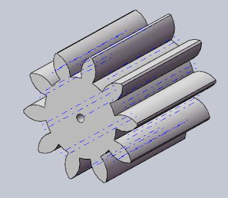
Set both the gear in an appropriate position as shown.

16. Select the center axis or any other faces. I have selected the bore faces. Set the ratio to 1:1 as they are same gear and finally click OK. You can try with different sizes of gears.

Your gears are ready to animate. Try to drag any of the gear and see the other gear rotate. You can also add a rotary motor to animate the gears.
This feature is an add-ins, so we have to activate it beforehand. I myself set my SW so that this add-ins will instantly active whenever i use Solidworks
Here's how we can do it :
1. go to Tools > Add-Ins. Make sure Toolbox/Toolbox browser is checked. If not then check them to add.
2. Click on the right side on Design Library and Select Toolbox. Next select Ansi Metric > Power Transmission > Gears. In side pane, you will see gears, racks, etc. RMB on Spur gear and select “Create Part”.

3. Set any properties of Spur Gear as desired. Click OK and then save your part.

4. Now click on “Make assembly from part/assembly” icon or File > Make assembly from part/assembly to start a new assembly.
5. Drop the gear anywhere in the assembly. It will get fixed by default.
6. Right Click on the part in the feature manager and select Float from the pop up window. This will remove the fix constraint from the part and make it free to move/rotate.
5. Drop the gear anywhere in the assembly. It will get fixed by default.
6. Right Click on the part in the feature manager and select Float from the pop up window. This will remove the fix constraint from the part and make it free to move/rotate.

7. Now show the temporary axis by View > Temporary Axis. You can also use part axis if there is any to proceed.


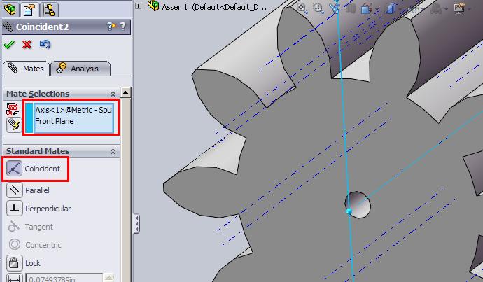
8. Select the appropriate plane (Front plane is this case) and click on Mate if it doesn’t pop up (as in pic) from the assembly toolbar, set a coincident mate between planes (Front,Right,Top) and axis.
9. Now the part is constrained in such a way that it can rotate free around its axis. Check it by dragging the gear. You will see the rotary movement only.
10. Select the gear in the workspace or feature manager and drag it while keeping the Ctrl button pressed. This will create a copy of the gear.
11. Mate the front faces of both the gear by adding a coincident mate between them.

12. Select the center axis of second/copied gear and appropriate plane (Top plane in this case) and add a coincident mate.

13. Select the center axis of second/copied gear again and either a plane or center axis of first gear (I have selected Front plane) and add distance mate. I have given 10mm. You can set the position by flipping the direction.

14. Now the second/copied gear is also free to rotate around its axis. Check this one also by dragging.
Set both the gear in an appropriate position as shown.
15. Click on Mate; go to mechanical mate and select gear mate.

16. Select the center axis or any other faces. I have selected the bore faces. Set the ratio to 1:1 as they are same gear and finally click OK. You can try with different sizes of gears.

Your gears are ready to animate. Try to drag any of the gear and see the other gear rotate. You can also add a rotary motor to animate the gears.
Written by Admin
ChromeGT is a modern, powerful and professional Blogger template made for your Portfolio, Business or almost any other kind of website.

0 comments: