tolerances - ISO tolerances
I've been working with machine for several years, and I learned that it is principally impossible to produce machine parts with absolute dimensional accuracy. In fact, it is not necessary or useful. It is quite sufficient that the actual dimension of the part is found between two limit dimensions and a permissible deviation is kept with production to ensure correct functioning of engineering products. The required level of accuracy of production of the given part is then given by the dimensional tolerance which is prescribed in the drawing. The production accuracy is prescribed with regards to the functionality of the product and to the economy of production as well.
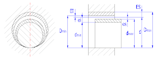
A coupling of two parts creates a fit whose functional character is determined by differences of their dimensions before their coupling.
where:
d=D ... basic size
Dmax , Dmin ... limits of size for the hole
dmax , dmin ... limits of size for the shaft
ES ... hole upper deviation
EI ... hole lower deviation
es ... shaft upper deviation
ei ... shaft lower deviation
Depending on the mutual position of tolerance zones of the coupled parts, 3 types of fit can be distinguished as : Clearance ; Transition ; Interference
The system of tolerances and fits ISO can be applied in tolerances and deviations of smooth parts and for fits created by their coupling. It is used particularly for cylindrical parts with round sections. Tolerances and deviations in this standard can also be applied in smooth parts of other sections. Similarly, the system can be used for coupling (fits) of cylindrical parts and for fits with parts having two parallel surfaces (e.g. fits of keys in grooves). The term "shaft", used in this standard has a wide meaning and serves for specification of all outer elements of the part, including those elements which do not have cylindrical shapes. Also, the term "hole" can be used for specification of all inner elements regardless of their shape.
The tolerance of a size is defined as the difference between the upper and lower limit dimensions of the part. In order to meet the requirements of various production branches for accuracy of the product, the system ISO implements 20 grades of accuracy. Each of the tolerances of this system is marked "IT" with attached grade of accuracy (IT01, IT0, IT1 ... IT18).
Field of use of individual tolerances of the system ISO:
If not in contradiction with constructional and technological requirements, preferably use some of the preferred fits such as :
- Clearance fits: H11/c11, H9/d9, H8/f7, H7/g6, H7/h6, C11/h11, D9/h9, F8/h7, G7/h6
- Transition fits: H7/k6, H7/n6, K7/h6, N7/h6
- Interference fits: H7/p6, H7/s6, H7/u6, P7/h6, S7/h6, U7/h6
Remember this : Tolerance must be given as rough as possible, as precise as necessary
A coupling of two parts creates a fit whose functional character is determined by differences of their dimensions before their coupling.
where:
d=D ... basic size
Dmax , Dmin ... limits of size for the hole
dmax , dmin ... limits of size for the shaft
ES ... hole upper deviation
EI ... hole lower deviation
es ... shaft upper deviation
ei ... shaft lower deviation
Depending on the mutual position of tolerance zones of the coupled parts, 3 types of fit can be distinguished as : Clearance ; Transition ; Interference
The system of tolerances and fits ISO can be applied in tolerances and deviations of smooth parts and for fits created by their coupling. It is used particularly for cylindrical parts with round sections. Tolerances and deviations in this standard can also be applied in smooth parts of other sections. Similarly, the system can be used for coupling (fits) of cylindrical parts and for fits with parts having two parallel surfaces (e.g. fits of keys in grooves). The term "shaft", used in this standard has a wide meaning and serves for specification of all outer elements of the part, including those elements which do not have cylindrical shapes. Also, the term "hole" can be used for specification of all inner elements regardless of their shape.
The tolerance of a size is defined as the difference between the upper and lower limit dimensions of the part. In order to meet the requirements of various production branches for accuracy of the product, the system ISO implements 20 grades of accuracy. Each of the tolerances of this system is marked "IT" with attached grade of accuracy (IT01, IT0, IT1 ... IT18).
Field of use of individual tolerances of the system ISO:
| IT1_IT6 | For production of gauges and measuring instruments |
| IT5_IT12 | For fits in precision and general engineering |
| IT11_IT16 | For production of semi-products |
| IT16_IT18 | For structures |
| IT11_IT18 | For specification of limit deviations of non-tolerated dimensions |
If not in contradiction with constructional and technological requirements, preferably use some of the preferred fits such as :
- Clearance fits: H11/c11, H9/d9, H8/f7, H7/g6, H7/h6, C11/h11, D9/h9, F8/h7, G7/h6
- Transition fits: H7/k6, H7/n6, K7/h6, N7/h6
- Interference fits: H7/p6, H7/s6, H7/u6, P7/h6, S7/h6, U7/h6
Remember this : Tolerance must be given as rough as possible, as precise as necessary


0 comments: